- Mechanical CADD
- Advanced Injection Mold Design
- Wirecut Training
- Architectural CADD
- Electrical CADD
- Civil CADD
- Advanced Auto Domain Training
- Plastic Technology
- Project Management


Amit Goswami
Call Us: +91 88 0285 0707
Center Head
Advanced Auto Domain Training

Fundamentals of Vehicle Design and Packaging
Automotive Chassis Training – NX-Unigraphics

Automotive Essentials Training– NX-Unigraphics
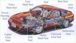
Automotive Interior Trim Training– NX-Unigraphics
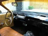
Automotive Powertrain Training– NX-Unigraphics

NX Automotive Structures Training– NX-Unigraphics
Fundamentals of Vehicle Design and Packaging

Course Content
History
- Introduction
- First Car, Front Engine, Alternative Propulsion
- Mass Production, Unibody, Art & Science
- Aero, People’s Car, 4X4
- Truck, Design With Passion, Passenger Priority
- Mid-Engine, British Roadster, Luxury SUV
- Downforce, Hatchback, Minivan
- Micro, XX LRG, Neighborhood Electric Vehicles
Getting Started
- Introduction
- Process Advanced and Production
- Systems Segments and Anatomy
- Step By Step Process One Through Four
- Step By Step Process Five Through Ten
- Designing With Sections Main
- Designing With Sections Rear View
- Grids, Ground Planes, Vehicle Attitudes, Tire Size, And Ride Height
- Hardpoints And Package Drawing
Functions & Segments
- Introduction
- Factors That Drive Functional Objectives and Applying Them to Architecture
- Vehicle Positioning
- Micro, Economy, Luxury, & Specialty Cars
- Minivans, SUV’s, Pickup Trucks, & Commercial Vans
Package Ideation
- Introduction
- Word Picture, Sketches, Ideation, and Unorthodox Thinking
Size & Proportion
- Introduction
- Size and Proportion, Key Dimensions, and Product Benchmarking
Occupant Packaging
- Introduction
- Manikin Anatomy and Occupant Environment Set-Up
Interiors & Cargo
- Introduction
- Instrument Panel & Control Set-Up
- Interior Volumes and Cargo
Powertrain
- Introduction
- Powertrain Anatomy & Selection
- Power, Engine Size, & Location
- Powertrain Layouts 1-4
- Powertrain Layouts 5-8 & Fuel Storage
Wheels & Tires
- Introduction
- Tire Sidewall, Wheel Flange, & Brakes
- Tire Envelopes, Spare, Tire Coverage, Tire-To-Body, & Steering
Suspension & Chassis
- Introduction
- Suspension Overview
- Suspension Systems
Bodies
- Introduction
- Load Paths & Types of Body Structures
- Sections, Design for Impact, Safety, & Material Application
- Body Closures, Side Aperture Design, & Cutlines
- Foot Swing, Door & Aperture Design, & Dropping Glass
- Windshield Aperture Design, Backlight, Aerodynamics, & Lighting
- Bumper Design, Ground Clearance, Glazing, & License Plates
Automotive Chassis Training- NX-Unigraphics
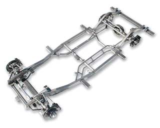
Course Contents
- Automotive Chassis Diploma Introduction
- Automotive Chassis Overview
Design Principles (AC)
- Design Principles Introduction
- Design Planning Stage
- Starting the CAD Model (AC)
- Modeling Best Practices (AC)
- Creation Methodology (AC)
- Settings and Rule (AC)
Design Modeling Techniques (AC)
- Design Modeling Techniques Introduction (AC)
- Modeling Creation Methods (AC)
- Clean Edge Modeling Technique (AC)
- Clean Edge Approach Bracket
- Shaping the Part (AC)
- Frame Rail Rough Shape
Draft (AC)
- Draft Introduction
- Part Draft using Taper
- Taper
- Taper Creation – Faces
- Taper Creation – From Edges
- Taper Creation – Tangent to Faces
- Taper Creation – Split Line
- Taper Editing
Parting Line Development (AC)
- Parting Lines Introduction
- Parting Lines Overview (PC)
- Project
- Projected Points and Curves Editing
- Intersect
- Intersection Curve Editing
- Section
- Subdivide Face
Thin – Walled Bodies (AC)
- Thin-walled Bodies Introduction (AC)
- Thin-walled Bodies (AC)
- Hollow
- Hollow Creation – Face
- Extract
- Extracting Faces
- Extracting a Region
- Thicken Sheet
Chassis Design Fundamental (AC)
- Chassis Design Fundamental Introduction (AC)
- Chassis Fundamental Overview
- Chassis Parts
- Chassis Design Fundamentals
- Creating Structural Darts
- Creating Flanges
- Frame Rail
- Crossmember Bracket
- Body Mount Bracket
Suspension and Steering Fundamentals (AC)
- Suspension and Steering Fundamentals Introduction
- Suspension and Steering Fundamentals Overview
- Suspension and Steering Parts and Operation Function
Evaluating the Part (AC)
- Evaluating the Part Introduction (AC)
- Evaluation Tools
- Face Analysis – Slope
Motion and FEA
- Motion and FEA Introduction
- Motion and FEA Overview
- Definition of Motion Application (AC)
- Mechanism and Motion Specific Terminology
- Motion Symbols
- Practical Uses of Motion
Scenario Environment
- Introduction – Scenario Environment
- Scenario Navigator
- Scenario Navigator Operations
- Master Model Dimension
- Materials
Motion Application Overview
- Introduction – Application Overview
- Motion Objects Overview
- Basic Articulation
- Motion Preferences
- Automatic Mating Condition Mapping
- Automatic Mating Condition Mapping – Using
- Listing Motion Connections
- Exporting an ADAMS Input File
Links and Markers
- Introduction – Links and Markers
- Link
- Link Creation
- Link Editing
- Link Information
- Marker Creation
- Marker Editing
- Marker Information
- Smart Point Creation
- Link Wireframe
Joints, Couplers, and Constraints
- Introduction – Joints
- Joints Overview
- Common Joint Parameters
- Revolute
- Slider
- Function Editor
- Joint Solids
- Universal
- Spherical
- Cylindrical
- Screw
- Planar
- Fixed
- Point on Curve
- Curve on Curve
- Rack and Pinion
- Gear
- Cable
- Joint Wireframe
- Joint Information
Post Processing
- Introduction – Post Processing
- Articulating the Mechanism
- Quick Drag
- Packaging Options
- Packaging Options – Measure
- Packaging Options – Trace
- Packaging Options – Interference
- Animation
- Spreadsheet Run
- Spreadsheet Run – Using
- Suspension Spreadsheet
- Graphs
- Graphing
- Graphing Jack
- Load Transfer
Finite Element Analysis
Fundamentals of Finite Element Analysis (FEA) – Introduction
FEA Overview
Strength of Materials
Structures Introduction
- Structures – Introduction
- Structures
- Structures – General Procedures
Creating a Scenario
- Creating a Scenario – Introduction
- Structures Manager
- Scenario Environments
- Scenario Environment- Defining
- Scenario1
Meshing Requirements
- Meshing Requirements – Introduction
- Meshing Requirements- Intended Use of Model
- Element Types
- Element Size and Count
- Material Type and Properties
Model Preparation
- Model Preparation – Introduction
- Midsurface
- Midsurface Creation Using Face Pairs
- Midsurface Creation Using Offset
- Midsurface Creation – User Defined
- Suppressing Features
- Feature Creation and Editing in Structures
- Idealize
- Mesh Mating Condition
- Master Model Dimension
- Model Variation Project
Loads
- Loads – Introduction
- Load Conditions
- Creating Loads
- Fatigue Load Variation
- Loads Project
Boundary Conditions
- Boundary Conditions – Introduction
- Boundary Conditions
- Boundary Conditions- Applying
- Boundary Conditions Project
Mesh Creation
- Mesh Creation – Introduction
- Automatic Meshing
- 3D Tetrahedral Mesh
- 3D Swept Mesh
- 2D Mesh- Creating
- 2D Mesh- Editing
- Mesh Checks for 2D Elements
- 1D Mesh- Creating
- 1D Element Section
- 1D Mesh- Creating Weld Elements
- Edge to Face Connection
- 1D Mesh Project
- Mesh Attributes
- Material Properties Project
- Rigid Connections Project
Quality Checks
- Quality Checks – Introduction
- Comprehensive
- Element Shapes
- Element Outlines
- Nodes
- 2D Element Normal
- Check 2D Mesh Project
- Check 3D Mesh Project
Solver
- Perform the Analysis – Introduction
- Nastran Solver Overview
- Linear Statics Plus Analysis
- Linear Analysis Solid Project
- Linear Analysis Shell Project
- Linear Static Axisymmetric Analysis
- Linear Buckling Analysis
- Normal Modes Analysis
- Crossmember Normal Modes Project
- Thermal Analysis
- Fatigue Analysis
Post Processor
- Postprocessor – Introduction
- Type
- Fringes
- Post Processor Project
- Identify
- Animation
- Display
- Animation Project
- View
- Auxiliary Scenario
- Crossmember Multiple Scenarios Project
- Hard Copy
- Quit
Automotive Essentials Training- NX-Unigraphics
Course Contents
Certification and Automotive Essentials Overview (AE)
- Automotive Essentials Diploma Overview Introduction
- Overview and Qualifications
- Automotive Essentials Overview
- Vehicle Systems
Drafting Workshop (AE)
- Drafting Workshop Introduction
- Drafting Overview
- Creating Views 1
- Creating Views 2
- View Preferences Project
- View Dependent Edits
- Drafting Style
- Tabular Note
- Parts List
- Drafting Workshop Task 1
- Drafting Workshop Task 2
Assembly Workshop (AE)
- Assemblies Workshop Introduction
- Assembly Design
- Chassis Assembly
Assembly Cloning (AE)
- Assembly Cloning Introduction
- Assembly Cloning Overview
- Cloning Assemblies
- Editing Existing Assemblies
Interpart Expressions (AE)
- Interpart Expressions Introduction
- Interpart Expressions
- Interpart Expressions – Creating and Editing
- Interpart Expressions- Using Expression Options
- Links
System-Based Modeling Overview (AE)
- System-based Modeling Overview Introduction
- System-Based Modeling Overview
- Applications
- Update Settings
- Geometry Linker
- Geometry – Creating
- Geometry – Editing
- Geometry – Management
- Information
- Simple System-based Modeling
System-Based Modeling Best Practices (AE)
- System-Based Modeling Best Practices Introduction
- System-Based Modeling Best Practices
- Design In Context
- In-Process Models
- Control Structures
- Modeling Errors
- Delayed Errors
- Circular References
- File Management
Component Filters (AE)
- Component Filters Introduction
- Filters and Zones
- Zone Creation
- Filters – Using with Load Options
- Scripts- Defining
- Filters and Zones – Best Practices
- Compressor Task 1
- Compressor Task 2
- Compressor Task 3
Representations (AE)
- Representations Introduction
- Representations
- Representations – Creating
- Assembly Hidden Line Removal
- Product Outline
- Product Outline – Defining
Product Data Management (AE)
- Product Data Management Introduction
- PDM Overview
- PDM Terminology
- PDM in the Automotive Industry
- PDM Data Storage
- PDM Workflow
- PDM Goals
- PDM Systems – Analysis and Comparison
- PDM Vehicle Configuration
Part File Standards (AE)
- Part File Standards Introduction
- Part File Standards Advantages
- CAD Standards – Setting
- Saving and Deleting Views
- Visualization
- Custom Views
- Layers
- Layer Category
- Object Display Preferences
- Visualization Preferences – Visual
- Visualization Preferences – Color Palette
- Visualization Preferences – Color Settings
- Properties – Part Attribute
Toolbars (AE)
- Toolbars Introduction
- Toolbars
- Toolbar Docking
- Toggle Toolbars
- User Tools
Resource Bar (AE)
- Resource Bar Introduction (SAE)
- Resource Bar
- Resource Bar Usage
- Palette Creation
- Resource Bar – Part Creation Using Templates
- Visualization Templates
- Drawing Template
- Navigator Properties
- Navigator Configuration
- Preparing a Seed File
Function of Part (AE)
- Function of Part Introduction
- Surface Complexity
- Dimensional Tolerances
- Design Time Versus Cost
- Stress Analysis
- Heat Treatments
Planning the Model (AE)
- Planning the Model Introduction
- Laying Out the Model
- Organizing the Model
- Beginning the Basic Model
- Smart Modeling Techniques
Electrical Systems Fundamentals (AE)
- Electrical Systems Fundamentals Introduction
- Electrical Routing
- Electrical Routing Terminology
Electrical Design Process (AE)
- Electrical Systems Fundamentals Introduction
- Basic Electrical Routing Procedure
- Qualifying Components
- Qualify Non-Electrical Components
- Qualifying Electrical Components
- Qualify Part – Clip
- Qualify Part – Connector
- Place Part Description
- Routing Paths – Creating
- Subdivide Segment
- Delete Path
- Logical Data and Physical Data
- Component List – Importing
- Connection List – Importing
- Filter Files – Importing
- Electrical Components – Manually Assign Unique IDs
- Create Terminals – Component List
- Components – Assign and Unassign
- Unmodel Terminals
- Routing and Unrouting Wires
- Routing Wires – Automatically
- Routing Wires – Manually
- Unrouting Wires
- Stock Offset Points – Creating
- Stock Offset Point – Point Method
- Creating Logical Associations
- Overstock
- Assigning Overstock
- Reports
- Reports – Accessing
Design for Manufacturing (AE)
- Design for Manufacturing Introduction
- Manufacturing Overview
- Machining Operations
- Remember the Tool
Industrial Processes and Materials (AE)
- Industrial Processes and Materials Introduction
- Automotive Materials and Processes
- Forging Overview
- Casting Overview
- Machining Operations Overview
- Sheet Metal Stamping/Hydroforming Overview
- Design for Manufacturing and Assembly
- Design for Specific Manufacturing Processes
Design for Manufacturing Modeling Methods (AE)
- Design for Manufacturing Modeling Methods Introduction
- Hub Forging
- Air Conditioner Compressor Bracket – Engine Mount
- Air Conditioner Compressor Bracket – Compressor Mount
- Air Conditioner Compressor Bracket – Machining
- Brake Module Bracket
Weldments (AE)
- Weldments Introduction
- Weldments Overview
- Modeling Weldments
- Weldments Using Promote
- Weldments Using Wave Geometry Linker
Tolerances (AE)
- Tolerances Introduction
- Tolerances Overview
- Tolerances in Design
- Tolerance Stacks
- Tolerance Stack Procedure
- Tolerance Allocation
- Managing Tolerances
Geometric Dimensioning and Tolerancing (AE)
- GD&T Introduction
- GD&T Overview
- GD&T Concepts
- GD&T Rules
- Datums
- Geometric Tolerances Types
- Form Tolerances
- Position Tolerances
- Profile Tolerances
- Virtual Condition
- Tolerance Stacks with GD&T
Sheet Metal Basics (AE)
- Sheet Metal Basics Introduction
- Sheet Metal Overview
- Sheet Metal Processes
- Sheet Metal Design Rules
- Sheet Metal Design
- Common Shapes
Sheet Metal Standards (AE)
- Sheet Metal Standards Introduction
- Parameter Standards
- Sheet Metal Preferences
- Global Parameters
- Checking Standards
- Standards File
Flanges (AE)
- Flanges Introduction
- Flange Creation
- Flange Restrictions
- Drill Press Task 4
- Enclosure Corner
- Bend Creation
- Flange Creation – Inset
- Door Task 1
- Bolt Task 1
- Profile Flange
- General Flange
- General Flange Creation – Parameters
- General Flange Creation – Build to Sections
- General Flange Creation – Build to Faces
- General Flange Creation – Punch Vector
Sheet Metal Features (AE)
- Sheet Metal Features Introduction
- Form/Unform
- Unbend/Rebend
- Direction Vector Definition for Sheet Metal Features
- Hole Creation – Sheet Metal
- Slot Creation – Sheet Metal
- Slot Formation
- Converting Form Features to Sheet Metal Features
- Door Task 2
- Cutout
- Relief
- Bead
- Punch
- Solid Punch
- Sheet Metal Features
- Bolt Task 2
- Door Task 3
- Edge Rip
- Corner
- Bracket
- Bracket
- Multibend Bracket
- Multibend Bracket Creation
- Strain
- MetaForm
Part in Process (AE)
- Part in Process Introduction
- Part In Process
- Part In Process – Using
Flat Patterns (AE)
- Flat Patterns Introduction
- Flat Pattern Preferences
- Flat Pattern Annotation Preferences
- Flat Patterns
- Flat Pattern Creation
- Flat Pattern Annotation
- Cutting Edges
Sheet Metal Assemblies and Drawings (AE)
- Sheet Metal Assemblies and Drawings Introduction
- Flat Patterns in Assemblies
- Flat Pattern Drawings
- Flat Pattern Drawing
- Flat Pattern Assembly
Automotive Interior Trim Training- NX-Unigraphics
Course Contents
Automotive Interior Trim
- Automotive Interior Trim Diploma Introduction
- Automotive Interior Trim Overview
- Styled Parts in Automotive Interior Trim
- Assemblies and Parametric Linking
Injection Molding (AIT)
- Injection Molding Introduction
- Injection Molding
- Mold Halves
- Wall Thickness
- Draft
- Flow
- Undercuts
- Openings
- Materials
- Material Selection
- Plastic Part Design CAD Process
Common Features (AIT)
- Common Features Introduction
- Ribs
- Snaps
- Living Hinges
Mold Design for Automotive Parts (AIT)
- Mold Design for Automotive Parts Introduction
- Mold Design for Automotive Parts Overview
- Designing Parts for Strength
- Designing Parts for Temperature
- Plastic Parts and Chemicals
Secondary Operations (AIT)
- Secondary Operations Introduction
- Machining
- Shielding
- Coatings
- Decorating
Preparing the Model (AIT)
- Preparing the Model Introduction
- Tool Considerations
- Scaling a Body
- Translation File Types
- Translating the Data
- Translators
- Translating Files
- Importing IGES, STEP, DXF and DWG Files
- Exporting IGES, STEP, DXF and DWG Files
- Heal Geometry
- Solid Creation
Draft (AIT)
- Draft Introduction
- Part Draft using Taper
- Taper
- Taper Creation – Faces
- Taper Creation – From Edges
- True Draft Taper
- Taper Creation – Tangent to Faces
- Taper Creation – Split Line
- Taper Editing
- Body Taper
Thin-Walled Bodies (AIT)
- Thin-Walled Bodies Introduction
- Thin-walled Bodies
- Hollow
- Hollow Creation – Face
- Hollow Creation – Region
- Hollow Creation – Body
- Hollow Editing
- Offset Face Creation
- Offset Face Editing
- Bosses and Cores
User Defined Features (AIT)
- User-Defined Features Introduction
- User Defined Features Overview
- User Defined Features – Advantages
- User Defined Feature – Configuring Libraries
- User Defined Feature – Creating Features with the Wizard
- Screw Boss UDF Creation
- User Defined Features – Inserting
- User Defined Features – Editing
- User Defined Features – Redefining
- Snap
- Screw Boss UDF Attach
Parting Lines (AIT)
- Parting Lines Introduction
- Parting Lines
- Offset
- Offset Curve Editing
- Project
- Projected Points and Curves Editing
- Combined Projection
- Combined Projection Editing
- Intersect
- Intersection Curve Editing
- Section
- Removing Associative Curve Parameters
- Subdivide Face
Surface Creation Using Strings (AIT)
- Surface Creation Using Strings Introduction
- Free Form Features
- Section String Selection
- Bounded Planes Creation
- Bounded Planes Editing
- Alignment Methods
- Simple Construction Method
- Through Curve Bodies Creation
- Through Curve Bodies Editing
- Through Curve Mesh Bodies
- Through Curve Mesh Bodies Creation
- Through Curve Mesh Bodies Editing
- Swept Bodies Creation Using One Guide String
- Swept Bodies Creation Using Multiple Guide Strings
- Swept Feature Editing
- Automotive Keyfob Task 1
- Automotive Keyfob Task 2
- Automotive Keyfob Task 3
Free Form Best Practices (AIT)
- Free Form Best Practices Introduction
- Free Form Feature Considerations
- Avoiding Problems in Free Form Features
- How to Fix Imperfect Faces Bodies
- Finding the Balance
Offset Surface Operations (AIT)
- Offset Surface Operations Introduction
- Offset Free Form Feature
- Offset Surface Editing
Feature Operations (AIT)
- Feature Operations Introduction
- Feature Operations
- Extract
- Extracting Associative Curves
- Extracting Faces
- Extracting a Region
- Extracting a Body
- Extract Feature Editing
- Trim Body
- Trim Body Editing
- Sewing Best Practices
- Sew
- Patch
Evaluating Plastic Parts (AIT)
- Evaluating Plastic Parts Introduction
- Evaluation Tools
- Object Information
- Point Information
- Distance Between Objects
- Angle Between Objects
- Minimum Radius
- Part Information
- Face Analysis – Slope
- Deviation Analysis
- Examine Geometry
- How to Fix Imperfect Faces Bodies
- Hollow Problems
Face and Soft Blends (AIT)
- Faces and Soft Blends Introduction
- Blend Creation – Face
- Blend Editing – Face
- Face Blend Edit
- Blend Creation – Soft
- Blend Editing – Soft
Editing Unparametric Sheet Bodies (AIT)
- Editing Unparametric Sheet Bodies Introduction
- Isoparametric Trim Divide
- Degree
- Stiffness
- Change Edge
- Boundary
- Reverse Normal
- Base Plate
Plastic Part Assemblies (AIT)
- Plastic Part Assemblies Introduction
- Plastic Part Assemblies
- Press Fits
- Snaps
- Snap Design
- Fasteners
- Bonding
- Ultrasonic Welding
- Other Welding Techniques
- Staking
Appendix (AIT)
- Appendix Introduction
- Glossary
- Common Materials
- Design Rules
- Resources
Automotive Powertrain Training- NX
Course Contents
Automotive Powertrain introduction
- Automotive Powertrain Diploma Introduction (AP)
- Automotive Powertrain Diploma Overview (AP)
Design Principles (AP)
- Design Principles Introduction
- Design Planning Stage
- Starting the CAD Model (AP)
- Modeling Best Practices (AP)
- Creation Methodology (AP)
- Settings and Rule (AP)
Design Modeling Techniques (AP)
- Design Modeling Techniques Introduction (AP)
- Modeling Creation Methods (AP)
- Clean Edge Modeling Technique (AP)
- Clean Edge Approach Bracket
- Shaping the Part (AP)
Draft (AP)
- Draft Introduction
- Part Draft using Taper
- Taper
- Taper Creation – Faces
- Taper Creation – From Edges
- Taper Creation – Tangent to Faces
- Taper Creation – Split Line
- Taper Editing
Parting Line Development (AP)
- Parting Lines Introduction
- Parting Lines Overview (PC)
- Project
- Projected Points and Curves Editing
- Intersect
- Intersection Curve Editing
- Section
- Subdivide Face
Thin – Walled Bodies (AP)
- Thin-walled Bodies Introduction (AP)
- Thin-walled Bodies (AP)
- Hollow
- Hollow Creation – Face
- Extract
- Extracting Faces
- Extracting a Region
- Thicken Sheet
Engine Fundamentals (AP)
- Powertrain Fundamentals Introduction
- Engine Fundamental Overview
- Engine Parts
- Engine Operation Function
- Engine Design Fundamentals
- Valve Cover Rough Shape
- Creating Flanges
- Casting Features
- Piston Design
- Pipe Design
- Tension Casting
Transmission Fundamentals (AP)
- Transmission Fundamentals Introduction
- Transmission Fundamental Overview
- Transmission Parts and Operation Function
HVAC Fundamentals (AP)
- HVAC Fundamentals Introduction
- HVAC Fundamentals Overview
- HVAC Parts and Operation Function
- HVAC Design Fundamentals
Evaluating the Part (AP)
- Evaluating the Part Introduction (AP)
- Evaluation Tools
- Face Analysis – Slope
Motion and FEA
- Motion and FEA Introduction
- Motion and FEA Overview
- Definition of Motion Application (AP)
- Mechanism and Motion Specific Terminology
- Motion Symbols
- Practical Uses of Motion
Scenario Environment
- Introduction – Scenario Environment
- Scenario Navigator
- Scenario Navigator Operations
- Master Model Dimension
- Materials
Motion Application Overview
- Introduction – Application Overview
- Motion Objects Overview
- Basic Articulation
- Motion Preferences
- Automatic Mating Condition Mapping
- Automatic Mating Condition Mapping – Using
- Listing Motion Connections
- Exporting an ADAMS Input File
Links and Markers
- Introduction – Links and Markers
- Link
- Link Creation
- Link Editing
- Link Information
- Marker Creation
- Marker Editing
- Marker Information
- Smart Point Creation
- Link Wireframe
Joints, Couplers, and Constraints
- Introduction – Joints
- Joints Overview
- Common Joint Parameters
- Revolute
- Slider
- Function Editor
- Joint Solids
- Universal
- Spherical
- Cylindrical
- Screw
- Planar
- Fixed
- Point on Curve
- Curve on Curve
- Rack and Pinion
- Gear
- Cable
- Joint Wireframe
- Joint Information
Post Processing
- Introduction – Post Processing
- Articulating the Mechanism
- Quick Drag
- Packaging Options
- Packaging Options – Measure
- Packaging Options – Trace
- Packaging Options – Interference
- Animation
- Spreadsheet Run
- Spreadsheet Run – Using
- Suspension Spreadsheet
- Graphs
- Graphing
- Graphing Jack
- Load Transfer
Finite Element Analysis
- Fundamentals of Finite Element Analysis (FEA) – Introduction
- FEA Overview
- Strength of Materials
Structures Introduction
- Structures – Introduction
- Structures
- Structures – General Procedures
Creating a Scenario
- Creating a Scenario – Introduction
- Structures Manager
- Scenario Environments
- Scenario Environment- Defining
- Scenario1
Meshing Requirements
- Meshing Requirements – Introduction
- Meshing Requirements- Intended Use of Model
- Element Types
- Element Size and Count
- Material Type and Properties
Model Preparation
- Model Preparation – Introduction
- Midsurface
- Midsurface Creation Using Face Pairs
- Midsurface Creation Using Offset
- Midsurface Creation – User Defined
- Suppressing Features
- Feature Creation and Editing in Structures
- Idealize
- Mesh Mating Condition
- Master Model Dimension
- Model Variation Project
Loads
- Loads – Introduction
- Load Conditions
- Creating Loads
- Fatigue Load Variation
- Loads Project
Boundary Conditions
- Boundary Conditions – Introduction
- Boundary Conditions
- Boundary Conditions- Applying
- Boundary Conditions Project
Mesh Creation
- Mesh Creation – Introduction
- Automatic Meshing
- 3D Tetrahedral Mesh
- 3D Swept Mesh
- 2D Mesh- Creating
- 2D Mesh- Editing
- Mesh Checks for 2D Elements
- 1D Mesh- Creating
- 1D Element Section
- 1D Mesh- Creating Weld Elements
- Edge to Face Connection
- 1D Mesh Project
- Mesh Attributes
- Material Properties Project
- Rigid Connections Project
Quality Checks
- Quality Checks – Introduction
- Comprehensive
- Element Shapes
- Element Outlines
- Nodes
- 2D Element Normal
- Check 2D Mesh Project
- Check 3D Mesh Project
Solver
- Perform the Analysis – Introduction
- Nastran Solver Overview
- Linear Statics Plus Analysis
- Linear Analysis Solid Project
- Linear Analysis Shell Project
- Linear Static Axisymmetric Analysis
- Linear Buckling Analysis
- Normal Modes Analysis
- Crossmember Normal Modes Project
- Thermal Analysis
- Fatigue Analysis
Post Processor
- Postprocessor – Introduction
- Type
- Fringes
- Post Processor Project
- Identify
- Animation
- Display
- Animation Project
- View
- Auxiliary Scenario
- Crossmember Multiple Scenarios Project
- Hard Copy
- Quit
Automotive Structures Training- NX-Unigraphics
Automotive Structures (AS)
Course Contents
- Automotive Structures Diploma Introduction
- Automotive Structures Diploma Overview
Body in White Design Principles (AS)
- Body in White Design Principles Introduction
- BIW Design Overview
- BIW Design Process
- Parts in Body in White Design
- BIW – Planning Stage
- BIW – Starting the CAD Model
Die Design and Tooling (AS)
- Die Design and Tooling Introduction
- Die Design Overview
- Die Design Structure
- Die Design Advantages and Disadvantages
- Die Tooling Design
Body in White Design Modeling (AS)
- Body in White Introduction
- Model Creation Methods
- BIW – Clean Edge Modeling Technique
- BIW – Clean Edge Application
- BIW – Shaping the Part Overview
- BIW – Rough Shape Envelope Creation
- BIW – Front Hinge Pillar Envelope
- BIW – Shaping the Part
- BIW – Stamped Depressions
- BIW – Complex Depression Creation Techniques
- BIW – Complex Depressions on Contoured Surface
- BIW – Fuel Filler Depression
- BIW – Front Hinge Pillar Depressions
- BIW – Flanges for Stamped Sheet Metal
- BIW – Flange Creation
- BIW – Offset Flange
- BIW – Door Inner Flange
- BIW – Front Hinge Pillar Flanges
- BIW – Beads
- BIW – Bead Creation
- BIW – Front Hinge Pillar Bead
- Dart Creation
- BIW – Dart Creation Using Tool Solids
- BIW – Front Hinge Pillar Completion
- BIW – Roof Bow Development


